This time I have one great and one even greater news for you.
The first great news is that a new major release of the best 3ds file reader (Ab3d.Reader3ds) brings some great new features to the library.
And an even greater news is that all this come with greatly reduced price. For example, the price for Ab3d.Reader3ds single developer library has been lower from $489 to only $199! Prices for Viewer3ds and for team and site developer license have been also reduced accordingly. To see the new prices, please visit our Purchase page.
And now to new features of the 9th major version of the library.
The library is mostly used for reading 3D models into WPF applications where the models are shown. But because of the great accuracy of importing 3ds file (in some cases the library imports 3D models even when 3D Studio Max does not import the models) the library is sometimes used as a converter to some other data format – for example to read 3D models from 3ds file and create an objective C code that defines 3D objects for iOS application.
Such custom converter applications read 3D models from 3ds file into WPF 3D models and then convert that models into some other data format. But the problem with such approach is that some of the data is lost when converting to WPF objects. For example if 3ds file defines materials with bump and reflection map, those two textures are not available in WPF. Also when 3ds file contains animations, the animation can be played in WPF application, but you were not able to access the raw animation data.
With the new version of Ab3d.Reader3ds you are now able to get all the materials and animation key frames data that are stored in 3ds file.
The materials data can be get with the new Materials3ds dictionary on Reader3ds object. The key in the dictionary represents the model name. The model name is the same as in the NamedObjects dictionary (note that you can get all the names of the objects with running the DumpNamedObjects method in Visual Studio immediate window after the 3ds file has been read). The value in the Materials3ds dictionary represents a new Material3ds type. This type contains all the material data that are defined in 3ds file specification. The Material3ds type also contains a Maps list that contain all the maps (textures) used by the material. 3ds file support the following map type: DiffuseColor (the only one supported in WPF), SpecularLevel, Opacity, Bump and Reflection.
The following Class diagram shows all the fields of Material3ds and MaterialMap3ds:

It may appear that there are many fields defined for materials. But compared to animation data, materials are really elementary. The Class diagram for animation data is as follows:
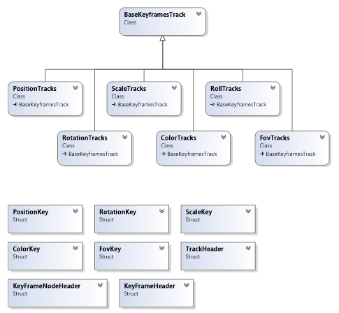
And that are only the classes. Each class also defines their own fields.
The key frame data can be get with calling the new GetKeyFramesData method. The method takes the model name as parameter and returns a list of BaseKeyframesTrack objects (for example PositionTracks and RotationTracks).
Each Tracks object defines their own array of Keys that define data about the object at specific time. For example PositionTracks use PositionKeys to define different positions of object at various time stamps.
To demonstrate the ability to get raw 3ds file data I have added a new sample to Reader3dsSamples project. With the sample users can drag and drop 3ds files to the sample Window and see the materials and key frames data for the 3ds file.
The next very interesting new feature of the new version of Reader3ds is that now it is possible to get the OptimizedMeshGeometry3D object for any 3D model read from 3ds file. The OptimizedMeshGeometry3D is a simple struct that is defined with the following code:
public struct OptimizedMeshGeometry3D
{
    public List<Point3D> Positions;
    public List<Vector3D> Normals;
    public List<Point> TextureCoordinates;
    public List<Int32> TriangleIndices;
}
As you see this is very similar to WPF’s MeshGeometry3D. The field names are the same, but the types of collections are fundamentally different. The OptimizedMeshGeometry3D uses simple Lists but MeshGeometry3D uses Point3DCollection, Vector3DCollection, PointCollection and Int32Collection.
The difference between those two types of collections is that the simple Lists are very fast when accessing individual items in the list. On the other hand the collection used in MeshGeometry3D are much more complex – on each get or set the code checks if the call is done on the correct thread, then after a few other ifs the data is get to the underlying FrugalStructList that is also not well optimized for performance.
When the Positions[i] is converted into assembly language the getter from List is converted in only a few lines of code, but in the MeshGeometry3D many lines of assembly code is executed.
This means that if you want to manipulate the 3D models with changing the individual positions, texture coordinates or other low lever data, it is much faster to change the data in a List and then regenerate the Point3DCollection from the changed list then to modify the data inside the Point3DCollection. Also if you are just reading the positions (for example to calculate the bounds), it is much faster when reading data from List then from Point3DCollection.
So, to allow using the faster lists, it is now possible to get the OptimizedMeshGeometry3D for any model read from 3ds file with the new GetOptimizedMeshGeometry3D method.
To demonstrate the performance gains, there is also a new sample in the Reader3dsSamples project.
The following are some of the results get from this sample:
Start performance tests on models with 34.403 positions and with executing each test 10 times
  Calculate bounds with MeshGeometry3D: 20,464ms
  Calculate bounds with OptimizedMeshGeometry3D: 13,779ms
  Change positions with MeshGeometry3D: 84,531ms
  Change positions with MeshGeometry without disconnecting MeshGeometry3D: 363,597ms
  Change positions with OptimizedMeshGeometry3D: 7,788ms


Start performance tests on models with 1.644.282 positions and with executing each test 10 times
  Calculate bounds with MeshGeometry3D: 1001,744ms
  Calculate bounds with OptimizedMeshGeometry3D: 669,594ms
  Change positions with MeshGeometry3D: 4191,129ms
  Change positions with MeshGeometry without disconnecting MeshGeometry3D: 11469,894ms
  Change positions with OptimizedMeshGeometry3D: 493,173ms
As you can see, calculating bounds is almost 40% faster. Changing positions (y += 10) is almost 10 times faster! And this with already optimizing the code with disconnecting MeshGeometry3D object from its parent GeometryModel3D. Without disconnecting the MeshGeometry3D object, using OptimizedMeshGeometry3D is more than 20 times faster.
To see the full test code please check the source of the sample.
And this is not the end of improvements.
The new version also prevents a "cross thread access" exception that could be thrown when the Reader3ds instance is created on another thread then the Read method is called.
And lastly, the new version improves animating objects when the animation does not start at first frame. In some cases the previous version wrongly positioned the objects on frames before first frame.
I hope that you like the new improvements to the Reader3ds library.
To check the new features, please download the latest trial version from the Downloads page or use your User Account page to download the latest commercial version.
Let me finish with a great news for everyone that already own a Reader3ds license, but have expired updates period: because the license renewal price is calculated based on the current price, you can now renew the Redader3ds license with greatly reduced renewal price.