In this blog post I will show you how easy is to show Kinect skeleton as a 3D model.
To jump start into 3D programming we will be using WPF and Ab3d.PowerToys library. The library will help us with providing the standard 3D models that will be used to display the skeleton and cameras that can be easily controller by the user.
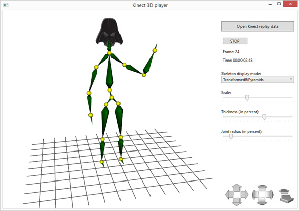
The image above shows us that the skeleton is created from yellow spheres that represent the joints and bi-pyramids are used to connect the joints together. To make the sample more interesting the skeleton has a Darth Wader’s head. Below the skeleton model a 3D wire grid is shown. It represents the floor.
In the lower right corner three different types of arrow buttons are shown. They can be used to control the camera – move, rotate and zoom in / out the camera. They are created by simply adding CameraControlPanel to the Window. Camera can be controlled also without using buttons. The MouseCameraController lets you rotate the camera with holding down the left mouse button, zoom in and out with mouse wheel and move the camera with holding control key and left mouse button. The MouseCameraController also provides easy way to specify different combinations of keys and mouse buttons for rotate and move actions.
Before diving into the code that shows the 3D model, let’s quickly look how we get the required 3D data from Kinect. Kinect SKD can provide real time skeleton and depth data. To make the sample work without having an actual Kinect device and an actual actor in front of the sensor, the Kinect data was saved into files with using Kinect Toolkit (an open source helper library). This way we can replay the recorded data any time we want.
For each recorded frame we get data for all recorded skeleton models. For each skeleton we get collection of joints and BoneOrientation objects. With them it is quite easy to get the actual 3D positions of the joints and the transformations (rotations and translations) applied on each of the joint. Once we have that data we can start on code that will show our 3D model.
In our sample we can show the 3D model in 4 different ways. User can change that by selecting different value in the “Skeleton display mode” ComboBox. The following are the available options:
- Lines,
- Pyramids,
- BiPyramids,
- TransformedBiPyramids
Using 3D lines
The simplest solution to show 3D model is to show it with 3D lines. Actually, if we would be using only standard WPF 3D objects without Ab3d.PowerToys, this would be the hardest solution to implement. The problem is that WPF 3D does not have native support for 3D lines and therefore they need to be created manually by defining the triangles that would show 3D line. Luckily Ab3d.PowerToys library adds that support to WPF. With the Ab3d.PowerToys library the code to add 3D line between two joints is the following:
AddSkeletonLines(Point3D startPoint, Point3D endPoint)
{
    var lineVisual3D = new LineVisual3D()
    {
        StartPosition = startPoint,
        EndPosition = endPoint,
        LineColor = Colors.Green,
        LineThickness = _skeletonThickness * 100.0
    };

    Placeholder3D.Children.Add(lineVisual3D);
}
The following image shows how the skeleton is shown when using 3D lines:
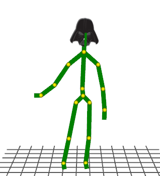
Note that it is very easy to define the line thickness.
Using pyramids
Using 3D lines already gives you some 3D feeling of the model, especially because you can rotate the camera around the model and observe it from any angle.
To give the model a better 3D look, we will use 3D pyramids to connect joints.
Because we need to orient the pyramid model based on start and end position, we cannot use standard pyramid model from Ab3d.PowerToys library. Instead we need to use a low level object - DirectedPyramidMesh3D. It can create a MeshGeometry3D that represent a pyramid oriented in such a way that the pyramid’s center is defined by start point and the pyramid’s top is define by end position.
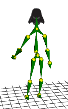
The following screenshot shows the skeleton displayed with pyramid:
Using bi-pyramids
Pyramids already gave us a better 3D representation that is more similar to actual 3D person model. But this can be further improved with using bi-pyramids. Bi-pyramids are objects that are created with combining two pyramids together.
We could easily create bi-pyramid with using two objects created with DirectedPyramidMesh3D. All we needed to do is to use the end position of the first directed pyramid as the start position of the second directed pyramid.
But to demonstrate some advanced features of the Ab3d.PowerToys we will create bi-pyramids with using lathe 3D objects. Lathe 3D object is an object that is defined by a 2D shape and start and end position. The 2D shape is than rotated around an axis defined by start and end position. This creates a 3D object – typical lathe objects are glasses and vases.
The following image shows a screenshot from samples that come with Ab3d.PowerToys library and show how a lathe 3D object was created (the 2D shape is shown on the right with red line):
The 2D shape used to define the lathe object is defined by LatheSections. Bi-pyramid is actually one of the simplest lathe objects possible – it requires only one section definition. This section defines how wide the bi-pyramid is.
After implementing the creation of bi-pyramids our skeleton looks like the first image in this blog.
From the list of display mode options you can see that it is also possible to show the skeleton as TransformedBiPyramids. This option shows the same skeleton as with bi-pyramids, but instead of using start and end position to define the object orientation, this time the transformation of the joint is used to rotate the bi-pyramid. This option provides a possible optimization. It can be achieved by creating the bi-pyramid model only once and then apply different transformation to it.
Similar optimization was used for showing joint spheres. Here we create only one instance of sphere GeometryModel3D and then use different transformations to position and scale the individual joint models around the skeleton.
The only thing yet to describe is how the head was created. We used a Darth Wader image and use it as a texture shown on a 3D plane. Once we have the position of the head and a head transformation, it is super easy to add Darth Wader head to the skeleton:
// Add head - show image for head
var headPosition = skeleton.Joints[JointType.Head].Position.ToPoint3D(_skeletonScale) + offset;

var headPlane = new PlaneVisual3D()
{
    CenterPosition = headPosition,
    Material = _headMaterial,
    BackMaterial = _headMaterial,
    HeightDirection = new Vector3D(0, 1, 0),
    Normal = new Vector3D(0, 0, 1),
    Size = new Size(_skeletonScale * 0.3, _skeletonScale * 0.3),
    Transform = skeleton.BoneOrientations[JointType.Head].AbsoluteRotation.ToRotateTransform3D(headPosition)
};

Placeholder3D.Children.Add(headPlane);
Adding special model for head finishes our 3D visualization of Kinect skeleton.
As you have seen, having the right tools makes the job very easy. And Ab3d.PowerToys library contains the ultimate collection of tools to add 3D content to your .Net application very easy. More about the library can be read from Ab3d.PowerToys web page.
The sample with full source code is available with Ab3d.PowerToys library. The trial version of the library can be downloaded from downloads page.